Building a Valved Reflux Column Still – A Step by Step Guide
The Story Behind the Build
Towards the end of 2017, I finally finished the reflux column still I’d been working on for a year, and that had been in various stages of planning for much longer than that. The result was everything I’d hoped for, and a considerable improvement over a crude device I’d once made back in my undergraduate days that consisted of a second-hand pressure cooker and a couple meters of copper tubing purloined from an abandoned building.
That dorm-room experiment was only marginally successful and was quickly forgotten, whereupon the urge to distill lay dormant for several decades. About the time I retired, I began to seriously consider building or acquiring a well-engineered distilling apparatus. There are many, many designs one can find on the Internet, from the quick-and-dirty (and sometimes dangerous!) devices that are little better than my fledgling attempt in college, to sophisticated column stills with those wonderfully eye-catching sight windows in the columns. There were also well-constructed kits for sale that my wife promptly informed me were beyond our budget, and even the cheapest locally-available, commercial pot still was priced at €2400 (nearly $3,000) but worse, this was a pot-still design that, without modification, would not give the quality of distillate I wanted to make. The only way forward was to build a column still myself, from scratch.
I offer this guide primarily for the benefit of European hobbyists who might not be able to find the parts specified by the predominantly US and Canadian plans available, but also to provide a workable example to all, since the basic design can easily be adapted to Imperial-sized components.
After much Internet research, I decided on a valved reflux column still as described in “Building A Home Distillation Apparatus“, an e-book of unknown authorship widely available on the Internet. There are indeed a few stills depicted on this site that faithfully follow those plans. However, since I live in Europe, the Imperial sizes specified for the tubing were not available. Moreover, a friend of the family who operates a plumbing-and-heating service assured me that couplings, elbows, reducers, and endcaps for the equivalent metric sizes were not easily come by. Thus, these would all have to be fabricated. In the end, I decided on 80mm copper pipe for the column and 120mm pipe for the condenser jacket. This tubing, intended for use as drains and downspouts, I sourced from the firm Apok (apok.be, Kampenhout, Belgium). Smaller tubing and fittings were obtained from local hardware stores or Amazon’s British and German affiliates. Copper and brass sheet can also be obtained from Apok, but these are huge, 1x2m sheets, are much more than needed, and are very expensive. Small squares, 20×20 and 10×20 can be obtained from the hobby-supply firm, Aduis (www.aduis.nl, Nijmegen). Raschig rings were supplied by the Swedish firm at partyman.com. The stainless-steel keg was obtained cheaply from a local brewer, since the dispenser valve, which I had no need for, was broken. Total cost of material, not including tools, was around €400. More than quarter of this was spent for the small, hard-to-find plumbing parts including elbows, endcaps, and hose barbs that had to be ordered online.
Photos of the Result
Below are some photos of the still and its components.
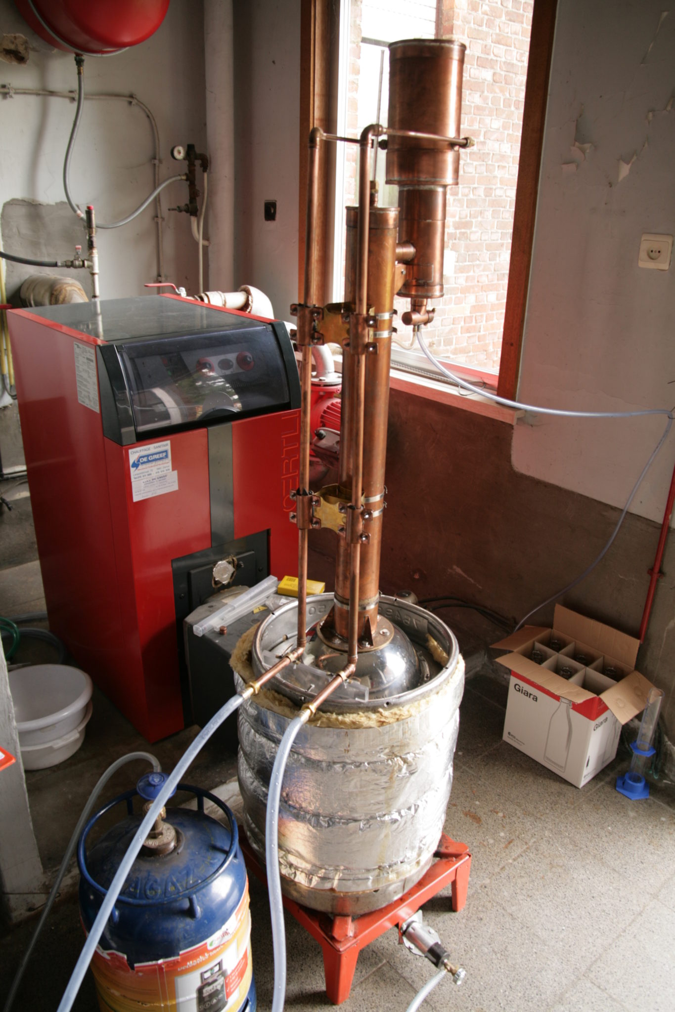
Figure 1. The completed still in operation in the laundry room. A good location needs a water source and drain, good ventilation to minimize the chance of a alcohol-vapor explosion and in this case, a reasonably high ceiling. The original planned location, our basement, had a ceiling that was too low for the still once it was sitting on the burner. (Note added in response to queries from friends: The large red box in the background is our oil furnace that heats the house.)
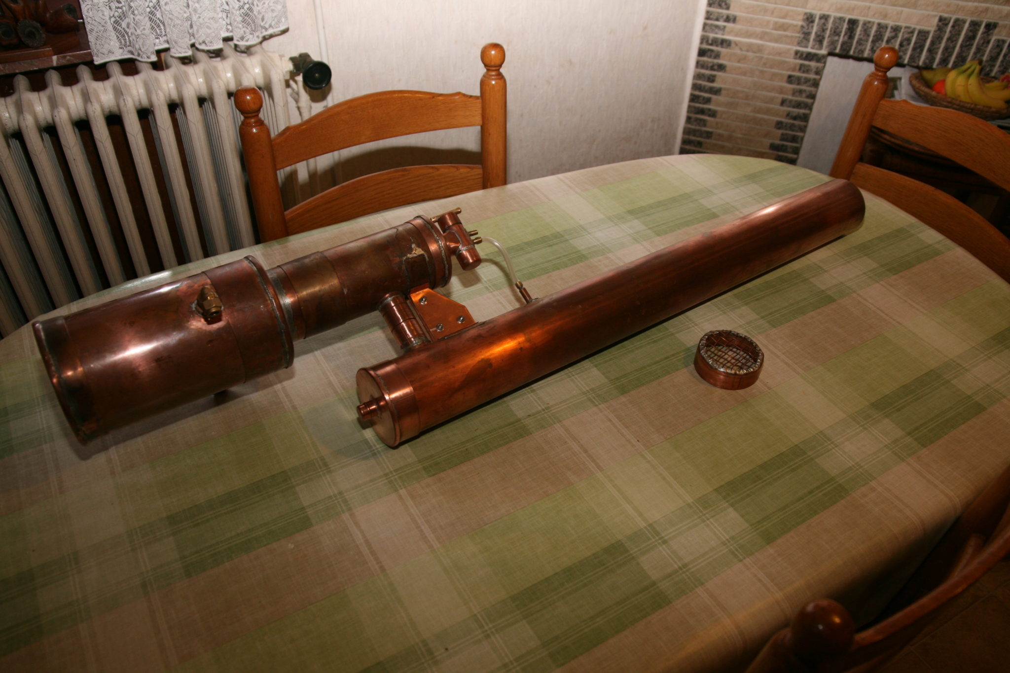
Figure 2. The column and condenser about midway though construction. Also shown is the column-packing retainer grid. After completion and initial testing, the neck of the condenser housing was shortened by a centimeter or two to improve efficiency, along with adding the internal “chimney” (not shown) to direct vapor into the center of the cooling coil.
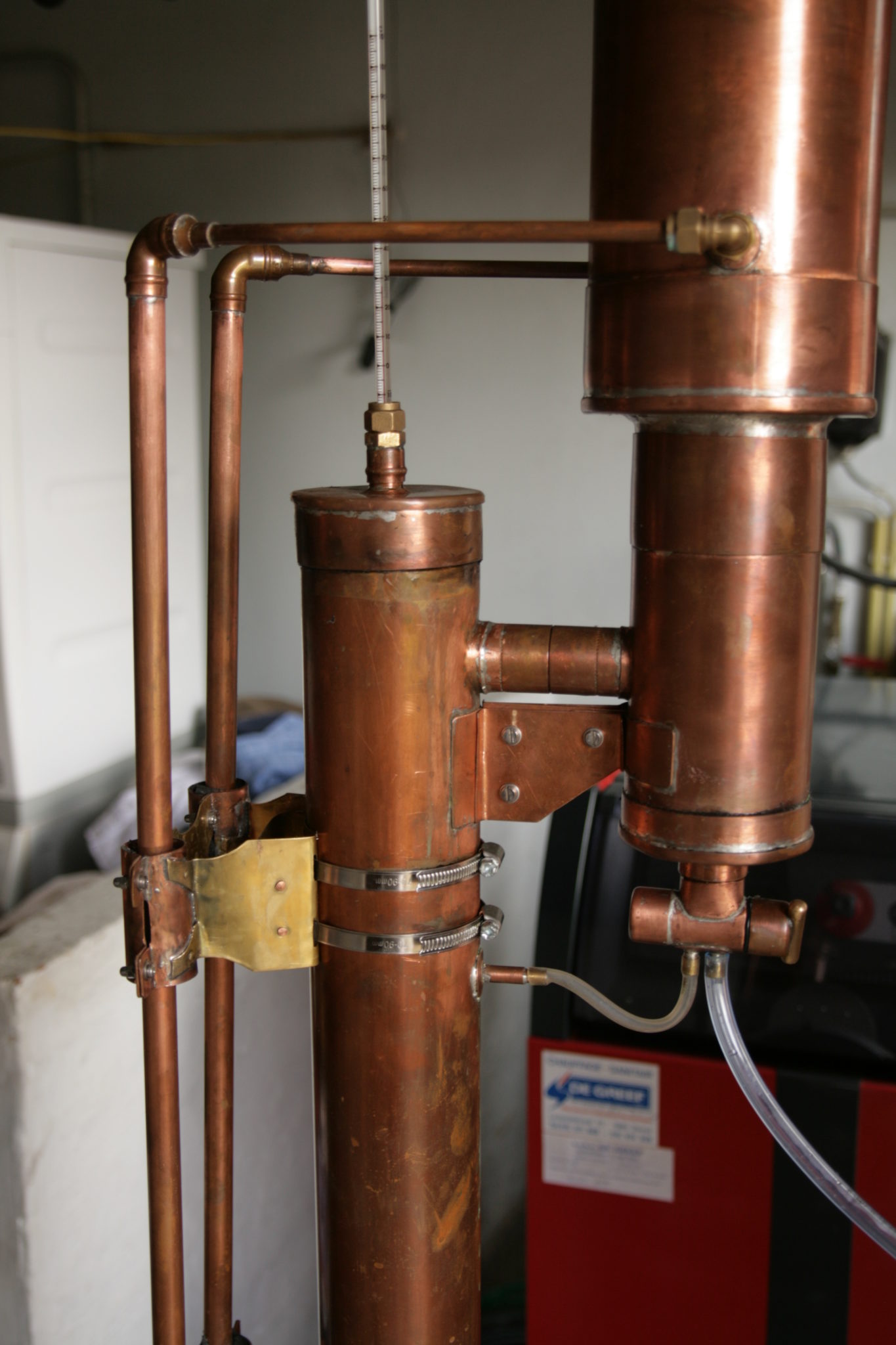
Figure 3. Closeup of upper part of still assembly. Note the thermometer coupling, waterline brackets, and the shorter condenser neck used in the final, working design. The cooling coil and vapor chimney, unfortunately, can’t be shown, since all joints that were not soldered, including the condenser lid, have been sealed into place with silicone gasket material.
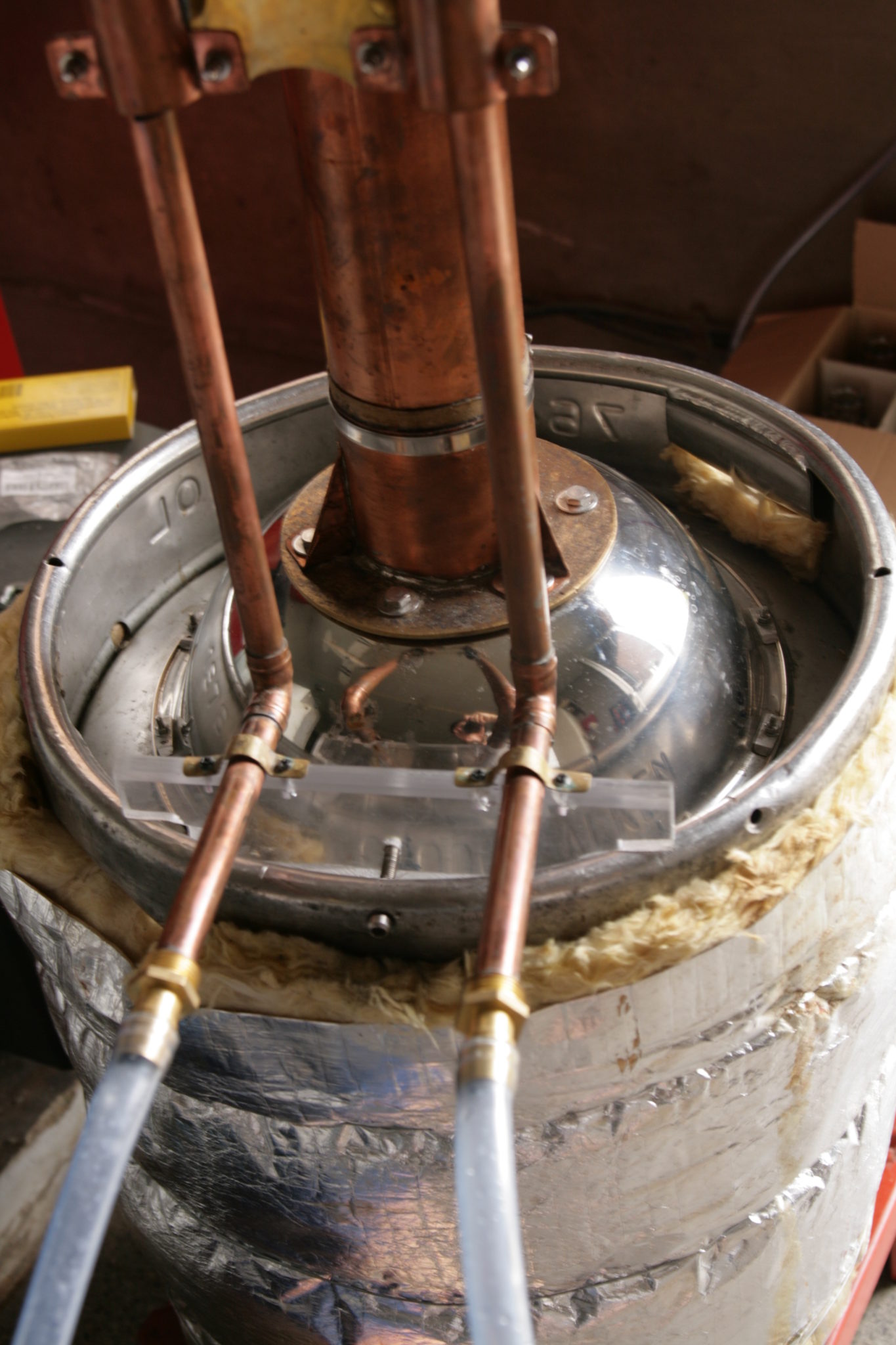
Figure 4. Closeup of lower part of column and stillpot. Here, it’s possible to see how the still is coupled to the insulated boiler. The column socket uses a length of connecting sleeve soldered and braced to the brass plate which in turn is bolted to the bottom of a stainless-steel bowl. In the foreground is the Plexiglass waterline support, bolted to the pot. To charge or clean the stillpot, this support is removed, as are the 12 bolts securing the bowl to the pot. A gasket and ring clamp insures a tight joint between the column and socket.
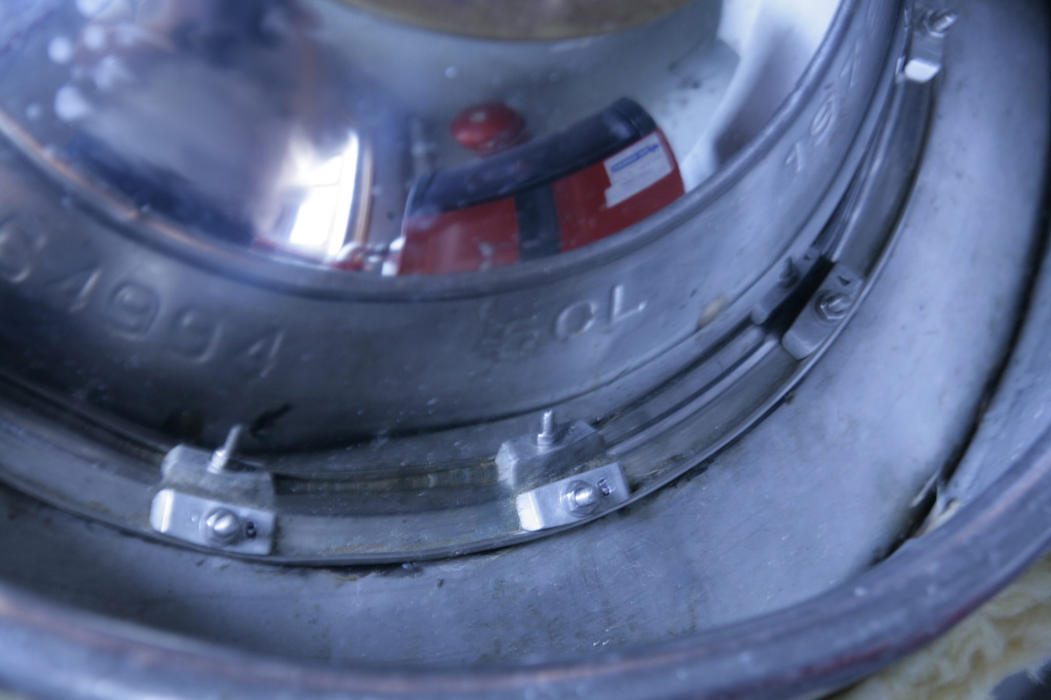
Figure 5. Closeup of bolts and aluminum hold-downs on rim of bowl. These were individually fitted, hence the stamped numbers to place each one on the proper bolt. Here, and where the brass plate joins onto the bottom (now at the top) of the bowl, a cellulose-fiber water- and heat-resistant gasket seals the joint.
Detailed Drawings and Description of Components
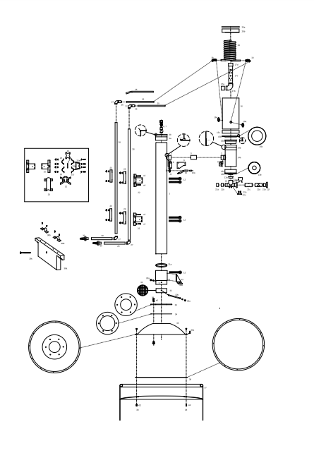
Figure 6. ‘Valved reflux still blueprint‘ showing all the parts used in assembling the still. This .pdf file will need to be downloaded, saved, and viewed with a .pdf viewer such as Adobe Reader because of the large size needed to display the necessary level of detail.
Explanation of numbered parts in drawing. What follows is a list of parts, components, and a brief description of how they were made. There are much easier stills to make than this one, but this design has proven itself capable of delivering near- azeotropic concentrations (90% +) of alcohol with sharp delineations between cuts. The reader will want to refer to the accompanying .pdf to see the parts described and their relationships to one another. In many cases, precise dimensions are not given. This is partly because the exact size is in most cases unimportant and partly because the builder will need to adapt dimensions during the build to obtain good fits. The .pdf blueprint will provide a good approximation of the size. The scale is 4:1, large enough to give good detail, but much too large to be printed out in its default size.
1. Reflux column. Copper tubing, .8x80x800mm. Copper pipe was purchased in 2m lengths and cut to size using a hacksaw. Each 2m piece of tubing had a 10cm-long “moff” (As the Dutch description calls it – literally a “muff”, but which is better translated as “sleeve”) on one end, a slightly expanded section to facilitate connecting lengths of pipe for use in downspouts, etc. Short sections of these “moffen”, cut to 2-3 cm length, were useful for creating the largest caps and connectors used in the design.
Straight cuts can be made in large, round pipe using a sheet of typing paper. This is wrapped tightly around the pipe, so that the ends precisely overlap, taped into place, and a line scribed around the pipe using the edge of the paper as a guide for sawing. Be sure to save all the scrap! By tossing scrap pieces of copper into the stainless stillpot, you can get the same beneficial effect as an all-copper still. The metallic copper is known for removing unpleasant-tasting sulfur compounds.
2. Coupling, 28mm i.d. The end of the coupling and the hole it fits in are flanged, to create a strong solder joint. All soldering that would come into contact with the distillate was a tin-based lead-free solder. To create such flanges, holes need to be cut a couple of mm undersize. For flanging, one can use pliers, but a small steel bar with a 3-4 mm-long slot cut in one end does the job more quickly, is easier to control, and avoids some of the scuffing one gets with pliers. Note that the rim of the condenser end of the coupling isn’t straight, and should be filed to match the curvature of the column before flanging, to assure a strong, tight fit.
3. Short piece of 28mm copper tubing to join column to condenser body. As with all joins that were not soldered, a liquid, quick-setting silicone gasket material was used to seal the joint. Smaller tubing was cut with a tube-cutter. This is an almost indispensable tool for getting smooth, straight cuts of copper tubing. Best to buy a good one, which will cut straighter, handle larger tubing, and not break (as my first, cheap one did).
4. Cap created using “moff” from the end of the 80mm tubing (4a) and a copper flat (4b) .8mm in thickness. Flat was cut slightly oversized, and bent down around the edge (with a slotted metal bar) to create a flange for a strong solder join to the circular section of moff. Center hole for thermometer coupling was cut slightly undersized and was flanged outward.
5. Short length 15mm copper tubing, flanged to match flange on cap, soldered into place. Precise length is not important, but needs to be at least as long as the 15mm endcap.
6. A 15mm i.d. endcap, drilled out to accept brass coupling (7)
7. Brass coupling for 1/4″ copper tubing. Inner threads filed flat and shortened, then coupling was soldered into cap (6). The compression ring or “olive” was discarded and replaced with a silcone O-ring to accommodate a thermometer.
8. Brackets cut from .8mm copper sheet to reinforce column-condenser connection. Soldered to column and condenser. Lead solder used here, since this was external to the still. Lead-tin solder is much easier to use than tin-copper or tin-copper-silver solders.
9. Brace made from 1mm copper plate for column-condenser bracket. Fixed in place with 3mm stainless-steel screws, washers, nuts (not shown). Though not shown here, but visible in the photographs, two more plates were eventually bolted onto the outsides of the brackets, for additional strength and stability.
10. Reflux return tube, 8mm copper tubing. A short piece of smaller brass tubing (to match 21h in size) soldered into the end. Return tube is placed so that outlet is centered inside column.
11. Copper ring, .8mm, to reinforce hole in column for reflux-return tube. This was slightly flanged outward around the inside, for additional rigidity.
12. Stainless-steel hose clamps to secure water pipe brackets to column and to secure column in column socket. Take care not to over-tighten these clamps! The thin-walled copper tubing will easily buckle if these are made too tight.
13. Reflux valve adapter. Subcomponents include a short length of 120mm moff (13c), a ring-shaped piece of 1mm copper plate (13b) and a short length of 28mm copper tubing (13a). Ring was flanged upward on the outer edge, downward along the inner edge, and sloped downward to form a very shallow funnel. Tubing was flanged outward at the top, to match the inner flange on the ring. Three pieces were joined with solder.
14. Condenser body formed from 80mm tubing and a length of 80mm moff. 28mm coupling attached as for (2). Section of moff formed an outer sleeve for the condenser adapter (15), adding stability and creating a better seal. Sleeve was soldered onto the condenser body.
15. Condenser adapter, similar in concept to the reflux valve adapter, consisting of sleeve made of 120mm moff (15c), flanged ring from 1mm copper plate (15b) and a section of 80mm pipe (15a). Pipe flanged at top, and tapered slightly at bottom by sawing 8 short vertical slots, pressing the pipe strips together, and soldering slots shut. This created a tight seal with the inside of the condenser body (14a), and another seal at the top of the moff-sleeve (14b).
16. Condenser jacket, a 20 cm section of 120x.7mm copper pipe. Copper washers (16a) soldered around tubing and onto condenser jacket to reinforce the point where condenser coil tubes exit.
17. Condenser chimney. This is a modification of the original Internet design that greatly improves condenser efficiency. Device uses a short piece of 28mm tubing (17a) to connect to inside of condenser inlet (2) via a 28mm i.d. elbow (17b). Into the top of this elbow goes a 150mm section of 28mm copper tubing perforated with holes that increase in diameter towards the top. This, at least theoretically, results on an even stream of vapor being directed onto the condenser coils. The perforated tube is capped with an ordinary 28mm i.d. copper endcap. This modification was added after the first trial, in which it became apparent that little of the vapor was being drawn up into condenser on its own. I consider this modification essential, and can easily be added to valved-reflux stills built following the original “Building a Home Distillation Apparatus” plans.
18. Two 10mm compression-type 90-degree couplings to attach water lines to condenser coil.
19. Condenser coil, consisting of 3m of 10mm copper tubing. Formed (with some difficulty) using a pipe bender. Choice of material is important here – there is rigid copper tubing, and there is malleable copper tubing. Experience quickly showed that the former can be very difficult to bend. In addition, three short sections of 10mm tubing and three 10mm i.d. 90-degree elbows were used to return the outlet down to the same level as the inlet. This was done purely for aesthetic reasons, though it also adds a few centimeters of cooling capacity. If the coil is configured this way, care must be taken to leave room for the perforated chimney: trial-fit everything before doing any soldering.
20. Cap, fabricated from short section of 120mm moff and 0.7mm copper plate. As with (4) edge of plate was turned down to create stronger solder bond.
21. Reflux valve, the most difficult and complex part of the build. This was fabricated partly because I was unable to find suitable needle valves (as per original plans) and partly because a single valve controlling both outlets makes more sense. With the partially-overlapping outlet grooves in the valve core (21d), a turn of this single valve can direct flow entirely to the reflux, entirely to collection, or any point between.
Tolerances are critical, and the degree of difficulty in attaching one component without overheating the entire piece and having other parts fall off requires attention, the use of wet rags to keep some parts cool, and the use of low-temperature solders for the later parts of the build. The valve proper attaches to the valve adapter using a piece of 28mm copper tubing (21g). One end of this tubing is flattened slightly in a vice, and then cut and filed to fit the 23mm i.d. copper coupling (21c) that forms the body of the valve.
The body is drilled with one central, large hole on the top for the inlet, and two slightly off-center holes in the bottom, for the reflux-return (bottom left) and collection outlets (bottom right). The left side of the valve body is closed using a short piece of 23mm tubing (21b) and a 23mm i.d. endcap (21a), soldered into the valve body. Note that when obtaining the 23mm coupling, the coupling must not have a ‘stop ring’ embossed into the center, as some do. It must be of uniform inner diameter for the entire length.
The valve’s flow-control core (21d) consists of an ordinary piece of 23mm copper tubing slightly longer than the coupling. A slot is cut in the top for the inlet, and two offset, but slightly overlapping, slots are cut into the bottom. By turning the core, output can be directed into the reflux return, collection outlet, or both. Onto the right end of the core are soldered an endcap and a handle made of brass rod. The rod is filed to shape so that it conforms to the top of the cap. The placement of this cap is critical. With the core in place, and contacting the left end-piece (21b), the end cap (21e) must either exactly contact the valve body (21c) on the right or leave exactly enough space for a suitable O-ring (not shown) between 21C and 21e. Otherwise, the valve will be prone to leakage. For use, the valve needs to be well-greased with a food-safe silicone lubricant.
Finally, two short lengths of brass tubing and a copper reinforcing grommet are soldered onto the bottom of the valve body (with low m.p. tin-bismuth solder). Care must be taken to match the shape of the grommet to the curvature of the valve body, and the two exit holes should be flanged outward, with matching flanges given to the brass tubes, such that everything fits flush against the valve body. Otherwise, there may be cross-leakage between the two outlets, which can be difficult to fix after everything has been soldered into place. To get good alignment between the tubes and the matching holes in the valve body, wooden dowels can be inserted through the tubes and into holes before soldering. This will also prevent solder from blocking the orifices.
22-24. Brackets for mounting water lines to column. These consist of a framework cut from .7mm semi-rigid brass plate (22) and copper half-rounds cut from 23mm copper tubing (23). Each frame consists of two pieces, a strip bent into a U with a 3-pronged “crowfoot” on each end (22a), and a U-shaped stiffening brace (22b) between the two legs of the frame. The brace is riveted in place using small copper nails cut to size, and is also soldered (lead-tin, as used throughout external cooling system components) to the frame. The toes of the crowfoot are bent in opposite directions (middle toe inward, top and bottom toes outward) to accept a copper half-round (23). The half-rounds are cut leaving flanges on the ends so that they can be bolted to their opposite halves. The inner halves are attached to the braces via the crowfoot (22c). These halves are riveted with copper rivets and soldered to the ‘toes’. The pairs of half-rounds are joined using 3mm stainless screws, washers, and acorn nuts. An additional brass fishplate (24) joins the inner four screw holes to add stiffness. For use, a fairly stiff foam tubing, such as used for air-conditioning and heating pipes, is placed between the tubing and the half rounds. This gives a solid, but slightly flexible fit, while also insulating the water lines from heat conducted from the hot column.
25. The 10mm copper tubing, about 150mm long, with a slight angle to accommodate the difference between the waterpipe spacing and the spacing between the outlets of the condenser. Here, again, the builder will want to mock everything up to find the exact length and get the fit correct before soldering tubing, elbows, and reducers in place.
26-29. Elbows (27) of 15mm i.d. and reducers (26) 15mm (o.d.) to 10mm (i.d) to feed 15mm water lines (28, 29) into condenser coil. One could, of course, use 10mm tubing for the entire length of the water supply, but 15mm was used for the vertical components because these were already on hand and because the heavier tubing helps counterbalance the weight of the condenser.
30. Three-quarter-inch (?) brass hose barbs. Although threaded, these were simply pressed onto the ends of the copper tubing and soldered into place, since the tubing fit inside the barbs. Unsure about the exact size – I simply took a short piece of tubing with me to a local hardware store and found a barb that would fit it.
31. column sleeve. This was part of the expanded moff and a short length of the adjoining 80mm tube, taken from one end of the 2m copper pipe. The moff didn’t really form a tight enough seal, so a gasket (31a) was added, and 6 1-cm slots cut into the top of the sleeve. This created enough slack that a hose clamp could be used to tighten the sleeve snugly around the gasket. Three triangular brackets were soldered onto the sides to add rigidity. These brackets match alternate screw holes in the base plate (33). The sleeve was also soldered directly to the base plate around the hole through which it passes.
32. Packing retainer. This basket-like component was made from a “tapstuk” (the Dutch name, meaning “bung-piece”) that was probably made to be soldered into the bottom of a rain gutter where it feeds into a downpipe. Shaped something like a narrow-brimmed top hat open at the crown, it fitted loosely inside the 80mm pipe. A 40mm length was cut from the “crown” and 20 equally-spaced holes drilled around the top. Cuts, 5 mm long, were made between these holes and the resulting strips bent over to form a rim. Their edges overlapped slightly, and were soldered to one another. Lengths of 1.5mm copper wire were cut, and the ends hooked through the holes and soldered into place, with the wires woven over and under one another in a basket-weave manner, to add strength. The retainer is held in place by a 4mm brass rod running through the column sleeve, with stainless steel washers and nuts threaded onto the ends.
33. Column base plate. This 4mm-thick brass plate has an interesting history. Rather than being something bought, it was originally a 25x15cm rectangular brass plate that I found with a metal detector near the ruin of the old watermill in our village. It appears to have been the cover to some sort of inspection hatch, and most likely came from the mill itself. As such, it would be on the order of 150 years old. This brass plate was polished (it was quite corroded as found), cut and drilled to become the base plate matching the flat area on the bottom of the Genware bowl. Sourcing a commercially available equivalent may be difficult. I suggest https://www.onlinemetals.com/. At any rate, it needs to be fairly thick for strength, since it must bear the considerable weight of the packed column and resist strong lateral forces if the mounted column is bumped or moved. Drilling the six evenly-spaced holes uses the compass-method that is described below in connection with placing the screw holes in the top of the keg.
34. Fiber gasket cut from sheet of gasket material.
35, 36. A 4-liter stainless steel salad bowl made by Genware, from Amazon.de. It was rather difficult to find a bowl of exactly the right shape and dimensions and that had a sufficiently wide rim to accommodate the 12 equally-spaced 3.5mm stainless screws used to secure it to the still’s boiler. Each screw is accompanied by an aluminum hold-down (35a) shaped to fit onto the bowl rim. Item 36 is the gasket cut using the bowl itself as a template.
37. Boiler, constructed from a 50l beer keg. A circular opening was cut in the top of the same diameter as the inside diameter of the Genware bowl. This was done using an angle grinder with a small cutting wheel to better accommodate the circular shape of the cut. Around the edge of the hole, twelve equally-spaced 3.2mm holes were drilled, and were tapped to accommodate 3.5 mm stainless-steel screws. These screws were inserted threaded-end up into the tapped holes after being dabbed with a bit of epoxy to hold them permanently in place. The sides of the boiler were insulated with fiberglass-aluminum foil insulation held on with wire hoops.
A cardboard template was used to mark the piece to be cut out from the top of the keg, using the bowl itself to draw the outer circle of the template, then a compass to draw a smaller (by the width of the bowl rim) inner circle. This ring was cut out and centered on the top of the keg, and the inner edge used as a guide for marking the line used for cutting out the top with the angle grinder. The rough edges left by the angle grinder will need to be smoothed with a grinder or file, to avoid cuts and scratches when cleaning the boiler.
To get 12 equally-spaced holes on the ring-template, a compass is first set to the distance from the exact center of the template to a point midway between the inner and outer edges – that is to say, in the middle of the bowl rim, where the screws will go. Mark the first screw hole at any point on the cardboard ring, then use the compass to mark the position of the next one, by placing the compass point on the first mark. Now place the point on the second mark to mark the third, and so on, all the way around the template. This will produce six equally-spaced marks. Now carefully set the compass for half that distance, and use the existing marks to place six more marks between the six original ones. For drilling the holes in the keg, it’s best to put the holes in the bowl first, then these holes can act as a template to mark the keg, to assure that one set of holes will exactly match the other! It’s important to drill the holes perpendicularly, which is somewhat difficult on the curved surface of the keg top, or the bowl will not easily slide onto the bolts. I used a drill press, but still found that the keg surface needed to be deeply center-punched to keep the bit from gliding off-course. Hard-metal bits and drilling paste are necessities for drilling stainless. If it turns out that the holes are not exactly perpendicular, small adjustments can be made by carefully bending the rim near the bolt hole slightly up, down, or to one side with a pair of vice-grips – but not so much that it can compromise the seal between the bowl and keg.
38. Thick Plexiglas plate (38a) to secure lower water lines to boiler/keg. This is notched at corners to snugly fit into curved rim of keg and held in place by stainless-steel bolt (38c) passing through a hole drilled into the top rim of the keg, with a corresponding hole in Plexiglas drilled and tapped to match. water pipes are secured to top of plate by means of brass brackets and screws (38b). I used the Plexiglas because I had it on hand, but a piece of lumber will do just as well. In this case, it’s probably not possible to tap threads into the wood, and the bolt will need to go all the way through, with a nut on the inner side.
In Conclusion
Thus far, this still has processed eight batches of 25-30l of wash, producing up to 2.5 liters of high-proof (80 – 90%) alcohol per run*. Rum and tequila (from agave syrup, ordered via the Internet), as well as rye and corn whiskeys have been successfully produced. Since reflux rates are kept fairly high to get good purity, distillation of the mash can take three or four hours, including warm-up and equilibration times. In operation, the user will want to first equilibrate for about twenty minutes at 100% reflux rate, then decrease the reflux to about 75-80% and start collecting product. As the alcohol percentage begins to decline below 90%, it’s necessary to continuously increase both the reflux rate and the amount of heat being applied to the boiler to keep the proof high while maintaining the flow rate. Towards the end of the run, when the temperature begins to rise rather dramatically and even high reflux rates can no longer maintain a low temperature and high output proof, the mid-run cut is over, and the rest is tails.
*Since publishing this article, I’ve found that by increasing the reflux rate to 80-90% reflux, and keeping the heat low, this column is capable of consistently producing virtually azeotropic alcohol, which is to say close to 95%. However, it takes patience, and about four hours, to distill 3 liters from a 30-liter batch at this rate.
Also, I’ve recently added a little sight glass between the column and the condenser, so I can easily see how much reflux is going back into the column. Unfortunately, it no longer seems to be possible to upload photos or I’d include one here.
Send Us Your Photo’s
If you’re building this valved reflux column still send us some pictures. We’ll post them below, just send them to learntomoonshine@gmail.com. Got a question about Steven’s valved reflux still build plan feel free to ask him in the comments below.
If you liked this plan you might also want to check out :
- Traditional Kentucky Whiskey Pot Still Plans – Learn How To Build A Pot Still At Home
- How To Make A Reflux Still – Complete Plans To Build A Homemade Still
- How To Build A Boka Reflux Still – Free Plan With Step by Step Instructions