Constructing a Spirit Still and Gin Basket
Why a Gin Basket?
My first few experiments in making gin proved to be a highly qualified success. It was drinkable, and a few individuals who tasted it even pronounced it good, though I suspect most were merely being polite. I have tried several methods starting with either alcohol distilled myself or using a middle-grade vodka, together with a selection of botanicals, mostly resembling some of the more standard recipes to be found on the Internet.
The first attempt consisted of simply macerating the botanicals in high-proof moonshine for about a week, then filtering. In this case, the coriander came through much too strongly, plus the resulting gin had the unappetizing color of a urine specimen and a tendency to ‘louche’, producing an unappealing haze when diluted in a cocktail. The alcohol was apparently dissolving some resinous compounds out of the juniper berries, which fell back out of solution when the water content became too high, as with absinthe. To avoid these contaminants, the second attempt consisted of simply adding the botanicals to vodka and immediately distilling the mixture together. The flavor was hardly an improvement, since the resulting gin now had a faint off-taste that I can only describe as resembling burnt cinnamon cookies. For the third attempt, I macerated and strained as in the first trial, but then distilled the filtrate. This gave by far the best result, but the juniper came through poorly and there was still something slightly amiss with the flavor, which seemed too ‘spicy’. It wasn’t bad, but it didn’t taste all that much like gin. At this point, a gin basket began to seem like a promising alternative. The online research I’d done seemed to indicate that a gin basket, as opposed to simple maceration or distilling the alcohol together with the botanicals, would give a superior, more delicately-flavored product.
The Project
Having already successfully tweaked my methodology so that the valved-reflux column I’d built, as described elsewhere on this website, now made a decent-tasting whiskey, I was up for another fabrication challenge. I decided that, to make decent gin, I would need to build a smaller spirit still, one that would incorporate a gin basket.
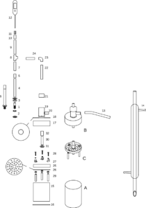
I already had most of the materials on hand for the build. I had acquired the necessary specialized tools and had a large pile of leftover components and scrap from the column build. More importantly, I had a 20l stainless steel pressure cooker that was ideal for use as the boiler. At one point in building my valved reflux column still, I’d acquired the pressure cooker, intending to use it as the boiler of the column still, but as plans progressed this proved too small for the purpose, and it had been abandoned in favor of a modified beer keg. Thus, as an added bonus, a gin still would at last put this €250 investment to good use. Work progressed quickly. Because materials were on-hand and because of skills gained in constructing the earlier column still, the entire project was completed in just a few weeks despite my working on it only whenever the mood struck. In the following step-by-step discussion of how the build was finally carried out, the reader will want to refer to the accompanying .pdf blueprint (Figure 1) to relate the numbers given in the text to the illustrations of the components. Below is a thumbnail of the plans. The full blueprint, which is too large and too detailed to display properly here, is available and can be downloaded from this link: Blue Print For Pot Still And Gin Basket
Figure 1. Thumbnail sketch of the gin basket and pot still hardware. The reader will need to download the .pdf mentioned above to view the details of the drawing.
The Spirit Still
The pressure cooker, a Lacor 71821 20-l had been chosen with an eye to easily replacing the pressure-valve nozzle with some sort of outlet suitable for a still. In this case, the nozzle was held in place with a simple nut and washer inside the lid. It was easily removed and replaced with a threaded brass tube (1) about 4 cm long. The tube was made from some 9mm brass rod, material left over from my reflux column build. This was made into a tube by boring it end-to-end in a drill press with a 4mm bit, then threading it on one end using an M8 metric die. This thread fit that of the original nut and washer (2) that had held the nozzle in place. Hint for centering the hole in the rod: Chuck the piece of rod into a drill and, at low speed, press the cut end into a piece of coarse sandpaper. The concentric scratches will show the exact center. Figure 2 shows the pressure cooker and some of the hardware during an early stage of construction with the spirit still itself complete, but with only the body of the gin basket completed.
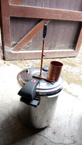
Figure 2. The pot still, and the gin basket during construction. The pot still is essentially complete at this stage, with the digital thermometer inserted in the top and the outlet tube detached and lying on top of the pressure cooker/boiler. Only the body of the gin basket was complete at this early stage.
To provide stability, and to insure a good seal with the upper surface of the pressure cooker lid, a bronze disk (3; made from an old Belgian 20-franc piece, but any thick copper or brass disk will do) was bored to 9mm and soldered to the brass tube just above the threaded part (see 6). A cellulose-fiber gasket completed the seal. A length of 10mm copper tubing (4) was pressed, using a vice, over the brass tube down to the disk and soldered into place, and a 10mm I.D. coupling (5) soldered to the top of the tube. All solder joints were made using lead-free, tin-copper-silver (99 : 0.7 : 0.3) solder. With high-tin solder, it’s essential to have very clean surfaces and use a zinc chloride flux to get it to wet the surfaces. With the higher melting temperatures of lead-free solders, a torch using MAPP gas, as opposed to propane or butane, is desirable but not essential.
The next sub-assembly consisted of two short lengths of 10mm tubing (7, 9) joined by a 3-way T connector (8). The digital thermometer (12) is attached with another short piece of 9mm brass rod, this time bored to the diameter of the thermometer and soldered into a 10mm coupling (11). Note that the tip of the thermometer should be at the outlet of the T connector (8). An outlet tube (13) and 30 cm glass Liebig condenser (14) complete the spirit still. The outlet tube should have a 15° downward bend in it close to where it attaches to the still.
Operating Principle of the Gin Basket
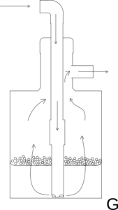
Figure 3 (G) illustrates the design of the gin basket, which resembles a tiny thumper keg, except that there should normally be no liquid in the bottom. Hot vapor enters the downpipe from above, exits from the bottom of the downpipe, rises upward, passing though the tray of botanicals, and exits through a horizontal tube at the top. Operating on the principle of steam distillation, this allows the vapor to absorb the delicate flavor elements of the botanicals without picking up the heavy oils and resins that maceration would add.
Gin Basket Body and Cover.
The main body is essentially a small copper tank made with 80mm copper pipe (A). The bottom consists of a circle of 0.8mm copper sheet cut a couple of millimeters over sized, so that it can be flanged upward around the edge, fitting tightly with the pipe and making a strong seam that’s easy to solder. These flanges are made using a small steel bar with a shallow slot sawed in the end; the edge of the copper sheet is placed in this slot and bent slightly, working around the perimeter and bending a little each time until the desired flange is obtained.
The lid was cut from the ‘outside’ end of a short copper sleeve, the original purpose of which is to join two sections of 80mm copper pipe, where one end slides inside a pipe, and the other end slides onto the outside of the adjoining pipe. By cutting sections from one end or the other of such a sleeve, one can create components that will fit snugly outside (17) or inside (25) the 80mm pipe. As with the bottom of the body, the circular top (18) of this lid was cut from 0.8 mm copper sheet, flanged, and soldered to the top of the 2cm sleeve section. In this case, the circular piece needed a hole in the center to accommodate the chimney-piece (19). The lid top was drilled in the center with a 10mm bit, then using a drill fitted with a rotary file, the hole was reamed until it was just slightly smaller than the chimney.
The chimney itself is simply a piece of 28mm copper tubing about 45mm long. After flanging the chimney hole upward, the chimney – also flanged, outward, around the bottom – would fit tightly in the hole while the matching flanges provided a strong solder joint. Finally, a 10mm hole was drilled into the side of the chimney, which was then enlarged slightly with a Dremel burr to accept a 10mm I.D. coupling that was soldered into place. Here, it was not possible to flange the edges of the hole in the chimney, but instead, the chimney end of the coupling was first filed slightly concave to fit the circular contour of the chimney, flanged slightly outward, then the coupling was inserted from the inside of the chimney, and soldered into place. Note here to be sure to make the chimney tall enough, leaving enough room above the output coupling so that the chimney cap (21) can slide completely down onto the chimney without bumping into the output coupling.
The chimney cap (21) consists of an ordinary 28mm I.D. copper endcap. This is also drilled in the center to 10mm to accept the inlet tube (22). For my purposes, the distance that this tube protrudes above the cap was adjusted (by cutting to length with a tube cutter) after soldering so that, with the gin basket just resting on the top of boiler, the elbow connector (23) was exactly even with the T-connector (8) on the boiler. The logic here was that, by letting the bottom of the gin basket rest on the top of the pressure cooker/boiler, the basket is kept hot enough to prevent condensation in the bottom.
The completed lid assembly is illustrated in (B) of the construction plan. Figure 3, below, shows a photo of the completed body of the gin basket and its cap.
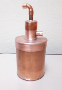
Figure 4, the body, lid, and inlet/outlet tubes of the complete gin basket, right. After this photo was taken, the vertical portion of the inlet tube, at the top, was shortened somewhat to match the height of the still outlet.
Botanical Tray
The botanical tray holds the herbs and spices used to flavor the gin, and slides snugly down into the gin basket body. It’s basic element is a disk of 0.7mm brass plate (26), drilled with 2.5 mm holes to form a sieve. Copper can also be used, but the brass was something I had on hand, and besides, it looks nice. This was soldered into a copper ring (25), a 20mm section cut from the ‘inside’ end of the same copper connecting sleeve from which an ‘outside’ section has been cut to form the gin basket cap. As with other joins, the edges of the ring and disk were flanged upward and inward, respectively to form a strong solder joint. Getting a nice, even, and eye-pleasing pattern of drill holes in the disk can be difficult, and is best done before mounting into the ring. I marked hole positions on mine using a compass to draw concentric circles and a ruler to mark radial lines. The intersections of the circles and the radii were then center-punched and drilled. A 10mm hole is drilled in the center for the lower downpipe to pass through.
The tray is supported by three legs (29). These are made from 40mm sections of the 9mm brass rod mentioned earlier, drilled about 15mm deep into the center of one end and then tapped to accept a 3mm stainless screw (28). Three equidistant holes are drilled near the edge of the brass disk for the screws, which are attached with nuts and washers, and then the feet are screwed onto the protruding screws. It is prudent to also add three brass eyelets (27), made from the same brass sheeting as the tray. The tray ring fits quite snugly in the basket body, and it can be difficult to pull out. With these eyelets attached, removal is easily accomplished with a stiff wire hook (made, in my case, from a spare bicycle spoke).
The eyelets themselves are simply small rectangles of brass plate, drilled on both ends (3mm on the bottom and 5mm on top) and bent into a right angle.
One of the trickier parts of the build is the lower section of downpipe (30-32). Note that this is not soldered to the tray, but is free-floating, and a copper disk (31; again made from a coin), soldered around the tube (30), rests on the tray surface, limiting how far the tube can slide down. To the top of this tube is soldered a 10mm I.D. connector (32) to receive the inlet from the upper section of the downtube (22). By leaving a bit of slack in the top of the connector between the upper and lower downtubes, so that the coupling can slide up and down over the upper tube by a few mm, the height of the tray, and thus the distance the outlet sits from the bottom of the tray, can be adjusted by screwing the three legs further on or off the screws holding them. The builder will want to trial-fit everything here before soldering, to get the dimensions correct so that the bottom of the lower downtube can be positioned either on or a few millimeters above the bottom of the gin basket body using leg adjustments.
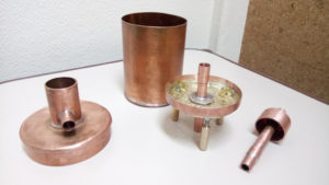
Figure 5, the completed gin basket, disassembled into its component parts. L to R, cap with chimney, body, botanical tray, upper portion of downtube and chimney cap.
It’s also a good idea to cut notches around the perimeter of the bottom of the lower downtube, so that the steam can escape even if the tube is resting on the bottom. A small round file does a fine job.
A word here on why the downpipe is in two sections: simply put, something needs to plug the center hole in the sieve to keep the botanicals from falling through. If the downpipe is a single piece, then it can only be inserted into the sieve hole by putting the lid on – and with the lid in place, you cannot dump in the herb mixture. I confess this was something I hadn’t thought of until the final assembly! The two-piece downpipe was a ‘fix’ implemented by cutting a 3-4mm section out of the middle of the downpipe with a tube cutter and soldering a coupling onto the bottom piece.
The system is designed so that the pot still can be used either with the gin basket, to make gin, or without it for use as a simple rectifying still. To use as a rectifying still, the outlet tube (13) is inserted directly into the outlet (8) of the still boiler. In either case, the glass condenser is attached to the outlet tube using a short length of soft plastic tubing. Figure 6 shows the entire assembly (less the cooling water lines) set up in our kitchen during a trial fit. In actual operation, I also cover the gin basket and most of the tubing with a thick towel, to provide insulation and keep all the parts hot. This prevents liquid from condensing in the bottom of the basket. We don’t want a miniature thump keg here.
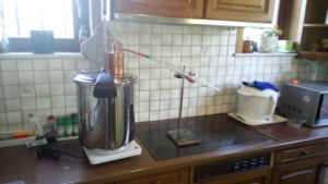
Figure 6. The gin still, set up and assembled in our kitchen. Heat is provided with an electric hotplate. Cooling-water lines, consisting of plastic tubing, are not attached in this photo. Note how the lengths of the copper tubing between the still and gin basket have been adjusted so that the basket rests on the lid of the pressure cooker, keeping it hot and preventing condensation inside the gin basket itself.
The Art of Gin
The gin basket method has indeed proved to produce a much lighter-tasting gin, free of any strange tastes, and one that was similar to commercial products. I find that the juniper is still a bit on the understated side, but presumably this can be remedied by using more juniper berries, though I’ve so far been careful not to go overboard here, lest I create something that tastes more like Pine-Sol than like gin.
Indeed, the actual gin ingredients remain a work in progress. The alcohol itself, however – there’s no need for any complicated grain mash – consists of a simple beet sugar and glucose mash (around 1.088-1.090 S.G.) fermented with a turbo yeast containing yeast nutrients. In distilling, one will want to take a fairly narrow midrun cut to get a nice, neutral alcohol.
The possibilities for the botanicals are almost limitless. I’d divide the possible ingredients into “essential” and “optional”. The essential ingredients would consist of juniper berries (50 parts), coriander seed (10-15 parts), and bitter orange peel (2-5 parts). Optional ingredients would include cardamom, angelica root, oris root, lemon peel, ginger, black pepper, and cinnamon (also 2-5 parts each). Precise amounts will depend on how fresh the ingredients are and on individual taste. Experimental ingredients tried and eliminated early on were rose hips, lemon grass, and Scotch pine blossoms. The plan for the next batch is to try adding a few tiny, immature cones from the Mediterranean cypress (those trees made famous by Van Gogh’s paintings) growing in our back yard. Though hardly a standard gin ingredient, these seem to smell the way I think gin should taste, and so should enhance the ‘juniperiness’ of the gin. Hopefully, these cypress cones won’t contain any psychoactive compounds that might make one want to paint disturbing impressionist landscapes or slice off an ear.
If you have any questions about how to build the spirit still and gin basket please ask in the comments section below and make sure you join our Facebook Group which is a great place to ask questions and get advice from other people.